Download PDF General Info Get Quotation
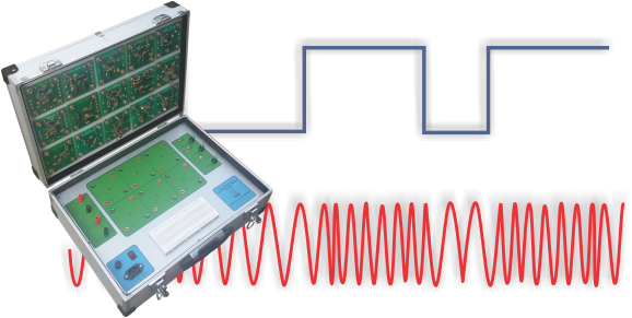
Analog and Digital Communication Trainer CT-3000 is a low cost high performance communication teaching system. It is design to provide all the basic tools necessary to conduct experiments in the field of digital and analog communication engineering, it can also be used for R&D projects in communication. It is designed to act as basic tool for carrying out experiments in the field of communication for Technical Colleges & Engineering Universities undergraduate and graduate courses. CT-3000 has built in RF crystal oscillator, AF oscillator and regulated +12 volts and +5 volts power supplies. In addition there is a wide variety of plug in modules available for different types of experiments to be performed.
This trainer is intended as a supplement to the textbook for communication course at junior, senior and graduate level students of electrical and electronics engineering, computer engineering and computer science. In addition, it can also be very useful for engineers from the industry who design and apply communication system in their products.
CT-3000 Communication Trainer comprises of a base unit, set of 19 modules and necessary interconnecting leads to carry out about twelve experiments in the field of analog and digital communication. A comprehensive manual is also provided along with the trainer. On the request more experiment can be added in the trainer.
Features
- Input voltage 220VAC 50Hz
- 10.24MHz crystal controlled R F signal source
- Low distortion 500Hz/1KHz AF signal source
- Clock with variable frequency 7Hz to 6KHz
- DC supply voltage +12V -12V 100mA and +5V at 1A
- 1 breadboard
- 6 sockets for modules
- Conveniently packed for inventory control
List of Experiments
- Familiarization with CT- 3000
- Demonstration of the clock generation from Manchester coded data
- Study of line coding and decoding techniques
- Study of the sampling theorem
- Study of two channel TDM system
- Study of Pulse Time Modulation
- Study of the FSK, PSK and ASK Modulations
- Study of PCM
- Study of Amplitude Modulation
- Study of Envelope Detector
- Study of Frequency Modulation
Add on Modules (Optional)
- SSB modulation and demodulation
- Clock and Data recovery modules
- BPSK / QPSK modulation and demodulation
- Delta modulation
List of Experiments
Data Generator Module
- NRZ1 11010100
- NRZ2 011111111
- NRZ3 10101111
- CLK 32KHz
4 Phase Clock Module
- This module outputs pulse trains of phases 0º, 90º, 180º and 270º at J2, J3, J4 and J5 respectively when clock signal is input at terminal J1.
FM Module
- This module generates frequency modulated carrier of center frequency about 88kHz at terminal J2 when AF modulating signal is applied at terminal J1.
Clock to Sine Converter Module
- This module generates synchronous sine and square waves output signals with controllable amplitude and frequency 1/8th of input clock.
Sample and Hold Module
- This module samples AF signal applied with sampling signal and outputs sampled signal.
Balanced Modulator
- The balanced modulator multiplies two input signals. It is used in synchronous demod of PSK and AMSC signals
Low Pass Filter Module
- This module two 2nd order active LPF with cut off frequencies of 500Hz and 1KHz.
FM Carrier Synchronizer Module
- This module generates AF signal phased locked with FM carrier signal input. The simultaneous display of AF and FM signals on scope results in stable waveforms on scope.
Pulse Time Modulation Module
- This module generates PWM and PPM signal when sample-and-hold AF signal and sampling signal reapplied.

