Download PDF General Info Get Quotation
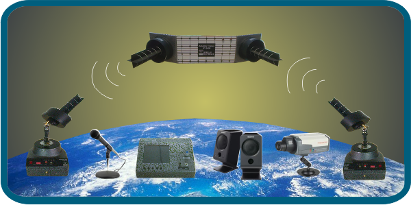
Satellite Communication Trainer ST-2400 is a low cost high performance Satellite Communication training system. It is designed for teaching and demonstrating basic Satellite Communication techniques and concepts for Technical Colleges and Engineering Universities for undergraduate and graduate courses.
ST-2400 can be conveniently placed in the laboratory. It can be placed at an elevation position if needed. The Satellite Transponder receives signal from Uplink Transmitter and retransmit at different frequency to a Downlink Receiver. The Uplink and Downlink frequencies can carry three signals i.e. Video, Audio and Data simultaneously. Any broadband signal or Digital/Analog data or function generator waveforms can be transmitted through this Satellite link. A large number of experiments can be conducted very easily on this Trainer.
Features
- Stand alone, Low cost system
- 2.42GHz synthesized source
- Microwave operation
- Safe low power output
- Variable propagation delay
- High RF output power and low noise
- More antennas can be added on the users course requirement
- Microphone and Speaker provided for Audio Link
- Conveniently packed for inventory control
- Helical Antennas(LHCP and RHCP) provided for transmitter, receiver and transponder
- Camera and Video Interface Card provided for Video Link
List of Experiments
- Establishing a direct communication link between Uplink Transmitter and Downlink Receiver using tone signal.
- To set up an Active Satellite link and demonstrate Link Fail Operation
- To establish an AUDIO-VIDEO satellite link between Transmitter and Receiver
- To communicate VOICE signal through satellite link
- To transmit and receive three separate signals (Audio, Video, Tone) simultaneously through satellite Link
- To transmit and receive PC data through satellite link
- To study the Radiation Pattern of Helical Antenna used in Satellite Trainer
- To study the Path Loss (Effect of Distance) between Transponder and Downlink Receiver
- To Study Depolarization effect due to polarization mismatch
- To establish PC-PC Link using satellite communication Link
- Study the fading effect due to different mediums
Accessories
- Uplink Transmitter
- Downlink Receiver
- Transponder
- Helical Antenna(3 LHCP, 2 RHCP)
- Video Camera
- Video interface card
- Microphone
- Speaker
- Audio/Video cables
- Data cable for RS232 interface
- AC power cables
- PC Serial communication
- Cables SMA (m) to SMA (m)
- Software CD
Specification
Uplink Transmitter
- Center Frequency: 2421MHz
- Output Power: 10 dBm
- RF.source: Syhtesized PLL
Downlink Receiver
- Center Frequency: 2477MHz
- Sensitivity:-85dBm
- Path Loss: 10dB typical
- RS232:
Helical Antenna
- AR: 1.1
- Directivity: 14.6
- HPBW: 37.5º
- FNBW: 83º
Transponder
- Uplink Frequency : 4 channels in 2.4 Ghz Band ; PLL Synthesized
- Downlink Frequency: 4 channels in 2.4 to 2.5 Ghz Band ;PLL Synthesized ISM Band
- RF Input Z : 50 Ohms SMA
- RF Output Z : 50 Ohms SMA
- RF output level : 0 dBm nominal
- Sensitivity : -85dBm
- Spurious output : - 30 dB typical
- Path Loss : 10 dB Typical
- Band limiting : 16MHz fixed typical
- Antennas : Helical
- Power Supply : 220VAC, 50Hz
- Accessories : Camera, Video to VGA converter Card, Cables BNC-BNC X2
- Signal fading: Variable 25dB
Camera
- Camera: Colour CCD Type
- Power Supply: From Tx
- Resolution: 420 Lines
- Size: 1/3" CCD
- Video O/P: 1Vp-p
Monitor
- Screen: 5" Colour LCD
- AV input: Analog
- Power Supply: 220
- Display Mode: 16 : 9
- Adjustable: Colour Brightness, Contrast,
Microphone and Speaker
- Audio 1 1KHz Tone / Ext Mic
- Mono Speaker

